
 Meco Man
d2c12e2da8
[RTduino] change the pinout group name
Meco Man
d2c12e2da8
[RTduino] change the pinout group name
|
1 year ago | |
|---|---|---|
| .. | ||
| README.md | 1 year ago | |
| README_zh.md | 1 year ago | |
| SConscript | 1 year ago | |
| nucleo-f412-pinout.png | 3 years ago | |
| pins_arduino.c | 1 year ago | |
| pins_arduino.h | 1 year ago | |
README.md
The Arduino Compatible for STM32F412 Nucleo Board
English | 中文
1 RTduino - Arduino Ecosystem Compatibility Layer for RT-Thread
STM32F412 Nucleo board has support RTduino. Users can use Arduino APIs, third party libraries and programming method to program on the board.
1.1 How to Enable RTduino
Please go to the RTduino repository to see the details.
Hardware Drivers Config --->
    Onboard Peripheral Drivers --->
        [*] Compatible with Arduino Ecosystem (RTduino)
2 Arduino Pinout
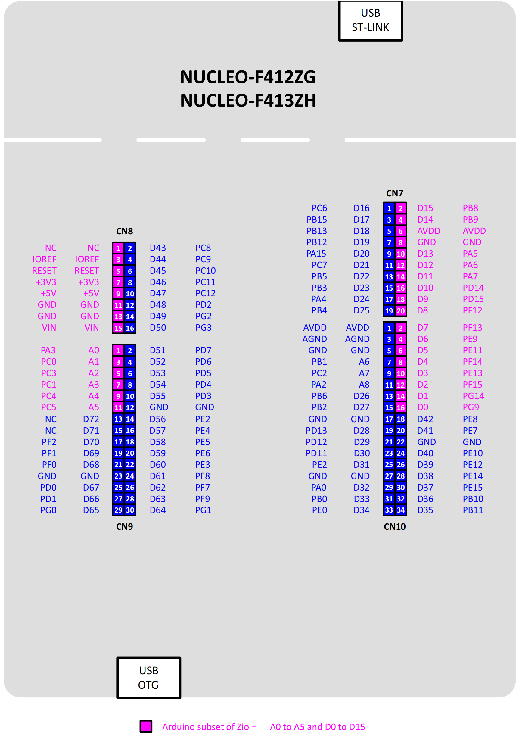
This board complies with Arduino UNO pins layout. For more details, please take a look at: pins_arduino.c and pins_arduino.h.
| Arduino Pin | STM32 Pin | 5V Tolerate | Note |
|---|---|---|---|
| 0 (D0) | PG9 | Yes | Serial-Rx. Token over by RT-Thread UART device by default |
| 1 (D1) | PG14 | Yes | Serial-Tx. Token over by RT-Thread UART device by default |
| 2 (D2) | PF15 | Yes | |
| 3 (D3) | PE13 | Yes | PWM1-CH3. Token over by RT-Thread PWM device by default |
| 4 (D4) | PF14 | Yes | |
| 5 (D5) | PE11 | Yes | PWM1-CH2. Token over by RT-Thread PWM device by default |
| 6 (D6) | PE9 | Yes | PWM1-CH1. Token over by RT-Thread PWM device by default |
| 7 (D7) | PF13 | Yes | |
| 8 (D8) | PF12 | Yes | |
| 9 (D9) | PD15 | Yes | PWM4-CH4. Token over by RT-Thread PWM device by default |
| 10 (D10) | PD14 | Yes | PWM4-CH3. Token over by RT-Thread PWM device by default |
| 11 (D11) | PA7 | Yes | PWM14-CH1. Token over by RT-Thread PWM device by default |
| 12 (D12) | PA6 | Yes | |
| 13 (D13) | PA5 | Yes | |
| 14 (D14) | PB9 | Yes | I2C-SDA. Token over by RT-Thread I2C device by default |
| 15 (D15) | PB8 | Yes | I2C-SCL. Token over by RT-Thread I2C device by default |
| 16 (D16) | PC13 | Yes | USER Button |
| 17 (D17, LED_BUILTIN) | PB0 | Yes | USER LED1 |
| 18 (D18) | PB7 | Yes | USER LED2 |
| 19 (D19) | PB14 | Yes | USER LED3 |
| A0 | PA3 | Yes | ADC1-CH3. Token over by RT-Thread ADC device by default |
| A1 | PC0 | Yes | ADC1-CH10. Token over by RT-Thread ADC device by default |
| A2 | PC3 | Yes | ADC1-CH13. Token over by RT-Thread ADC device by default |
| A3 | PC1 | Yes | ADC1-CH11. Token over by RT-Thread ADC device by default |
| A4 | PC4 | Yes | ADC1-CH14. Token over by RT-Thread ADC device by default |
| A5 | PC5 | Yes | ADC1-CH15. Token over by RT-Thread ADC device by default |
| A6 | -- | On-chip internal voltage sensor. ADC1-CH17. Token over by RT-Thread ADC device by default | |
| A7 | -- | On-chip internal temperature sensor. ADC1-CH16. Token over by RT-Thread ADC device by default |
Notice:
- Don't use a same hardware timer to drive PWM (analogRead) and servos at same time, because hardware timers can only generate a same frequency for 4 PWM channels. Otherwise, it could cause a failure when drive servos.
References
3 Communication
3.1 I2C Bus
I2C bus is SCL/D15 and SDA/D14 pins. Users can directly include the #include <Wire.h>, which is the Arduino official I2C header file, to use the I2C bus.
3.2 SPI Bus
The SPI bus of the Nucleo board is the CS/D10, MOSI/D11, MISO/D12 and SCK/D13 pins printed on the board. These D11, D12 and D13 pins It is taken over by the RT-Thread SPI device framework and there is no need to directly control these pins. User needs to operate D10 chip select pin. Directly quote #include <SPI.h> (Arduino official SPI header file) to use. After using the SPI function, the PWM function of D10 and D11 will be irreversibly disabled and converted to the SPI function.
3.3 Serial
This board supports to use Serial. method to operate uart3 device. See example.